

Graph App To Graph Pkain Design
Graphing
With over 100 built-in graph types, Origin makes it easy to create and customize publication-quality graphs. You can simply start with a built-in graph template and then customize every element of your graph to suit your needs. Easily add additional axes, as well as multiple panels/layers to your graph page. Save your settings as a custom template for repeat use. In addition, you can do batch plotting with other dataset.
Line & Symbol Graphs
Origin supports:
- Line plot
- Row-wise Line Series Plot
- Lollipop plot
- Scatter plot (with XY Error bar, Column Scatter, Drop line, Color Map, Size Map)
- Line + Symbol plot
- Area
- Stacked Area
- Fill Area
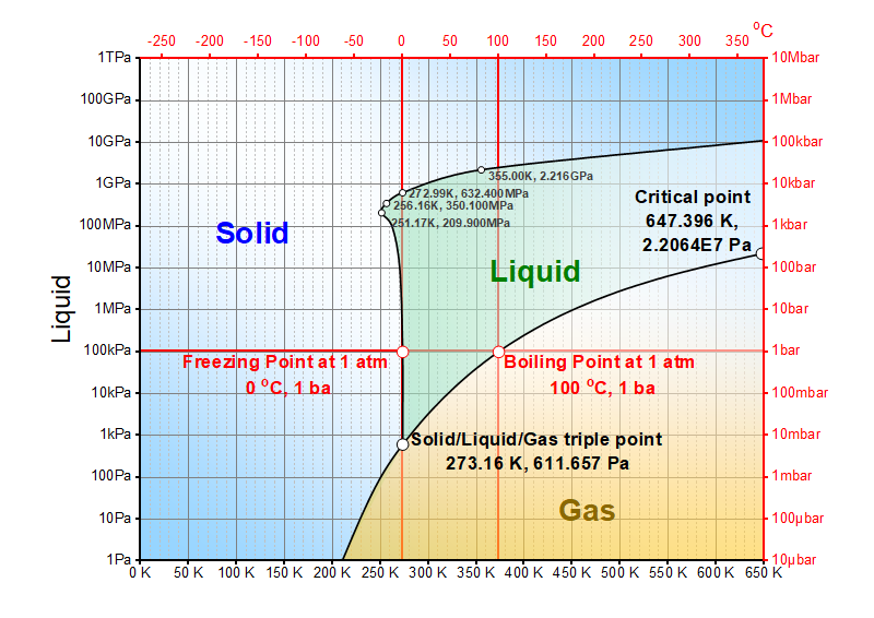
The graph displays pressure–temperature phase diagram of water. Area can be filled to specified plot or to specified axis to create such phase diagrams
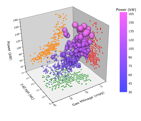
3D Color-Mapped Scatter Plot. Customization options include linking symbol size to another column (Engine Displacement) and enabling projections on all three axes planes.
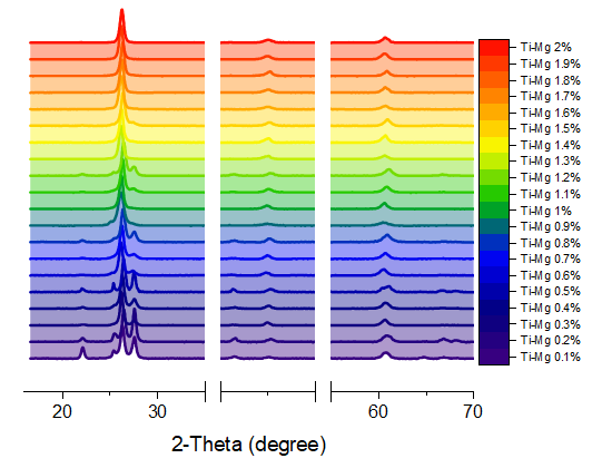
The stacked plot displays a series of spectra plotted with increasing offset.Area are fill to next plot. Two breaks are added on the X axis.
New Density Dots plot of 2 million data points. Colormap represents data density computed using a fast algorithm.
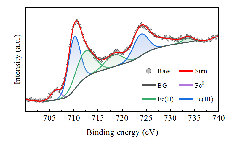
The graph displays XPS spectra with different composition measured. Area under the peaks curve are filled to specific data plot (baseline).
The graph can be easily created from an online template, XPS Area
Scatter plot depicting the isotope signature of N sources found in IAB iron meteorites. The graph is created by plotting the points with X and Y error bars while indexing symbol colors to distinguish between etched and un-etched samples. The bounding triangle is plotted by a dotted line plot. An additional scatter plot with labels is then added on the top line to show the mixing ratios for the two proposed sources.
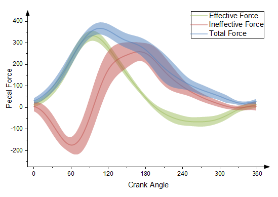
This graph displays three datasets with error bars.
The error bars have been set draw as lines with fill area. Transparency has been set to all three curves so that data in overlapping regions can be clearly seen.
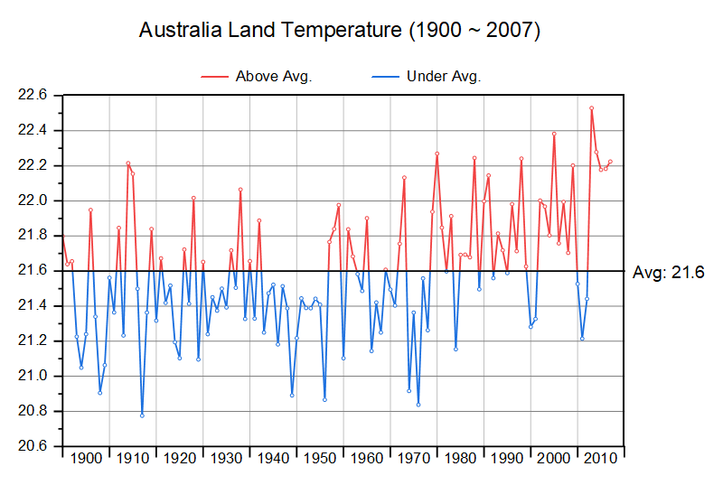
Origin supports anomaly plot which has different color in the upper and lower part. The anomaly plot can be line, columns or area
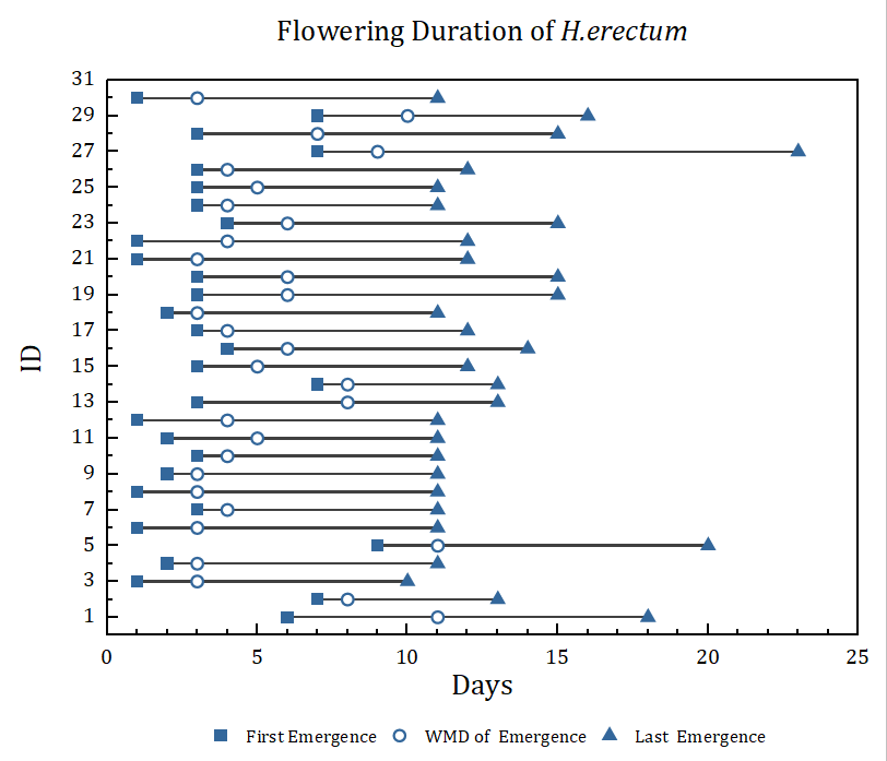
Lollipop plot of flowering duration data
Column & Bar Graphs
Column and Bar Charts are widely used across all fields, for their simplicity and ease of interpretation. Origin supports:
- Basic, stacked, grouped Column & Bar chart
- Basic, grouped Floating Column & Bar chart
- 3D Column chart
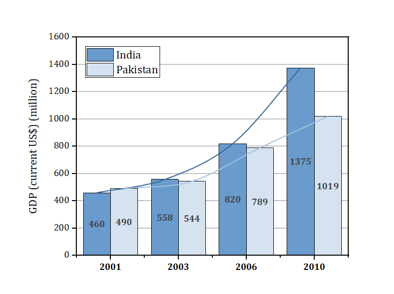
Basic bar graph with connected line to show the trends. The graph can be easily created from an online template, Bar with Connected Lines
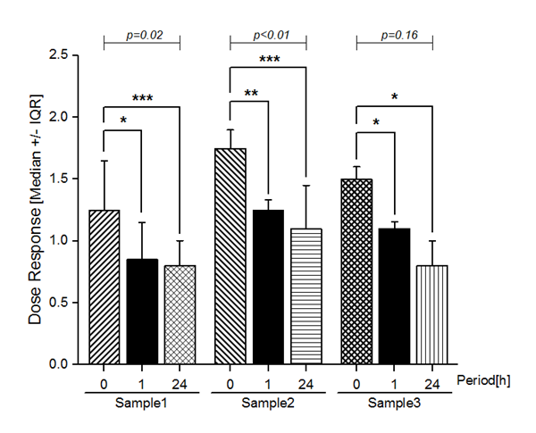
Grouped column plot with asterisk bracket to show significant differences. Options for customization include flexible spacing between subgroups, placement of asterisk brackets to highlight comparisons and patterns for each column.

A 3D bar plot on a flattened surface, showing the population distribution of the United States. This graph is created by flattening a 3D surface of US Map and then plotting the city population as 3D bars on it. The surface is set transparent. Add a 5-column plot to the right as a creative Legend.
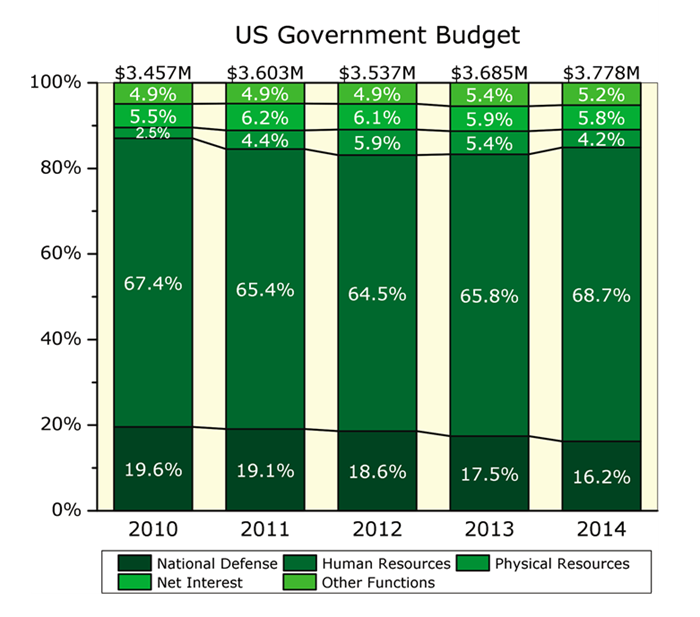
This graph displays a 100% stacked column plot with line connected
Pie and Doughnut Charts
Origin supports different kinds of pie and doughnut charts
- 3D Pie Chart
- 2D Pie Chart
- Doughnut Plot
- Pie Map
- Pie of Pie Plot
- Bar of Pie Plot
- Doughnut of Pie Plot
- Sunburst Plot
- Doughnut Plot with Total Wedge = 100
- Pie with Different Radius
- Doughnut with Different Radius
More Graphs>>
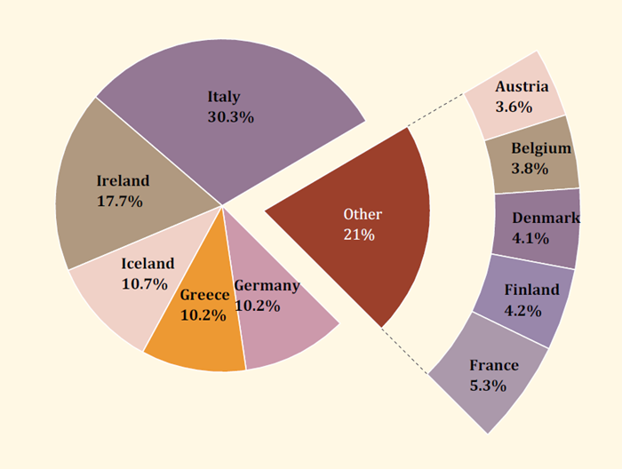
In the graph the wedges whose percentages are less than 5% are combined as one, and show as a part of doughnut plot. Origin also provide other options to show combined wedges as bar or pie
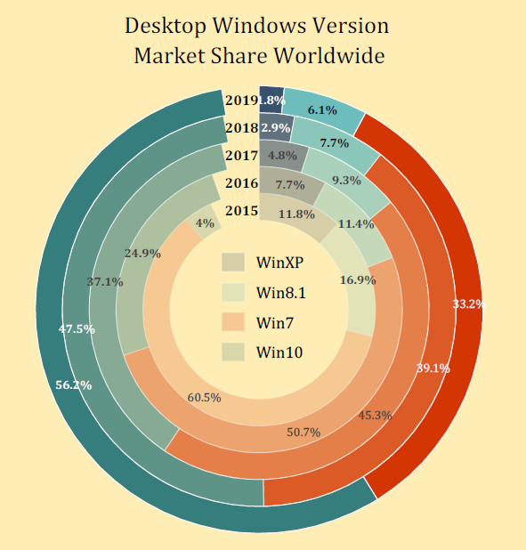
The example displays a chipped doughnut plot. The doughnut plot shows world market share by dominant desktop windows version, for years 2015 ~ 2019. Other versions are shown as a notch in the doughnut plot.
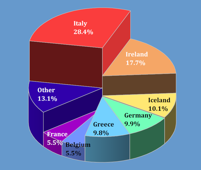
The example displays a 3D pie chart with slices of varying thicknesses. In the graph the wedges whose percentages are less than 5% are combined as one.
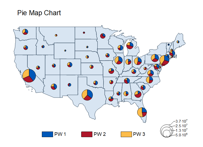
The pie map plot displays pie charts on specific locations. The USA map is overlaid on graph by OriginPro's build-in map data.
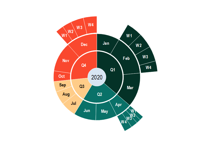
The graph is an example of a sunburst chart. A sunburst has multiple levels (represented by different rings), across which you can see how a category is split into contributing sub-categories.
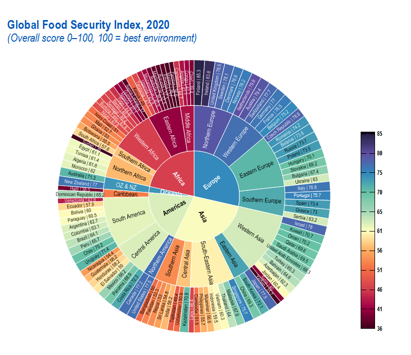
The graph is an example of a colormap sunburst chart. The color of the wedges is mapped to their value. For categories and subcategories, the color is decided by the mean value of category. The graph can be created from an online template, Colormap Sunburst
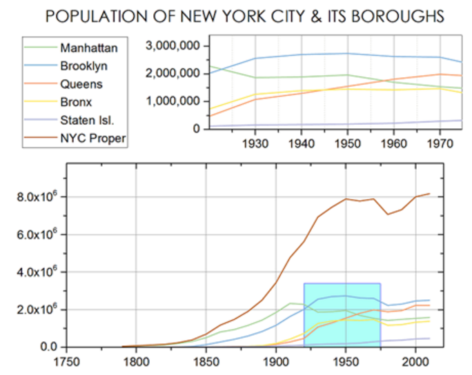
Multi-Axis & Multi-Panel Graphs
To present multiple datasets in the same graph window, Origin provides:
- Multi-axis graph
- Multi-panel graph
YBCO superconductor growth study using 3 sets of axes including Disposition Pressure, Annealing Temperature, and Delta Temperature over time. Additional customization includes cubic B-spline connection-type for the Delta Temperature line + symbol plot. Error bars (in both directions) are included for the Annealing Temperature scatter plot.
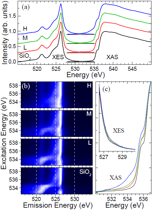
Multi-panel plot shows experimental x-ray emission (XES) and absorption (XAS) spectra. The graph contains seven layers. The upper and lower-right layers are grouped XES and XAS line plots, one with an inset plot. The four layers on the lower-left are X-axis-linked color fill contours. All layers can be resized and repositioned flexibly.
Multi-panel graph presenting high-resolution electron energy-loss spectra from a GaN surface. The three main panels present measured data (red filled circles) and calculations (solid blue line), with linked X axes and axis breaks added. The inset plots in the three panels display a section of the data (red fill circles with vertical drop-lines) for emphasis.
Waterfall Graphs
Origin's Waterfall graphs are ideal for comparing variations between multiple datasets created under similar conditions. The graph has a three-dimensional effect, enabling you to see variations in the Y or Z-direction.
- 2D Waterfall
- 3D Waterfall
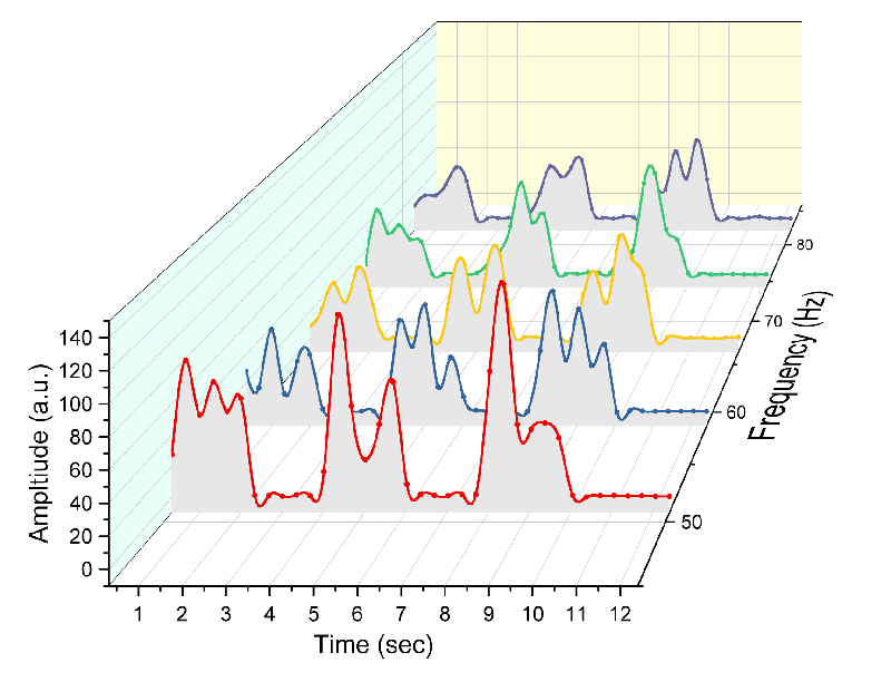
3D Waterfall supports Connect Control which enables watefall to have smooth lines even though data points are few.
Waterfall with a single traced value highlighted with different color. The line series are ungrouped so that the desired trace can be set to a different color.
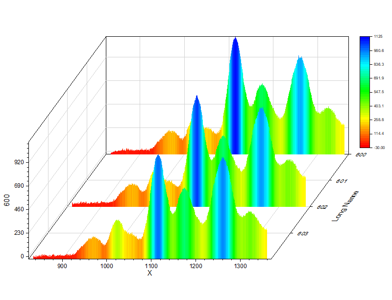
This is a waterfall plot, whose filled areas are colormapped to the curve value. The graph can be created from an online template, Colormap Filled Waterfall
2D waterfall graph with inset plot which displays a line connects maximum of each curve in waterfall. The graph can be created from an online template, Waterfall with Inset
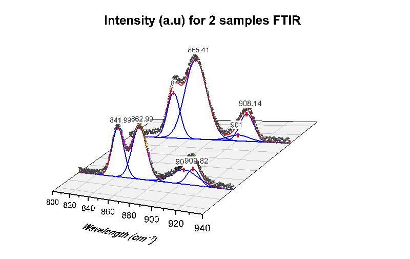
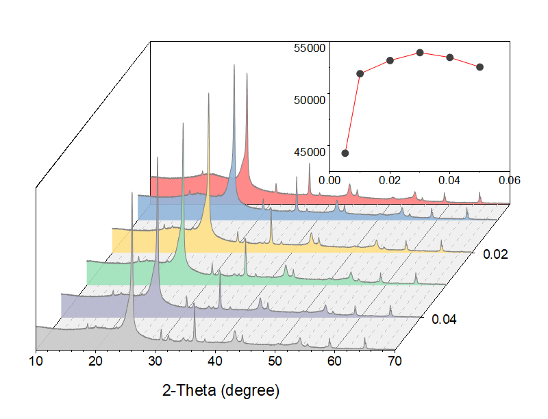
The is a waterfall graph to show two set of peak deconvolution results in three-dimension space. Each set of peak fitting curves are set to be located on the same position.
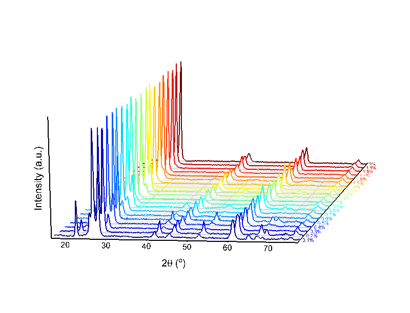
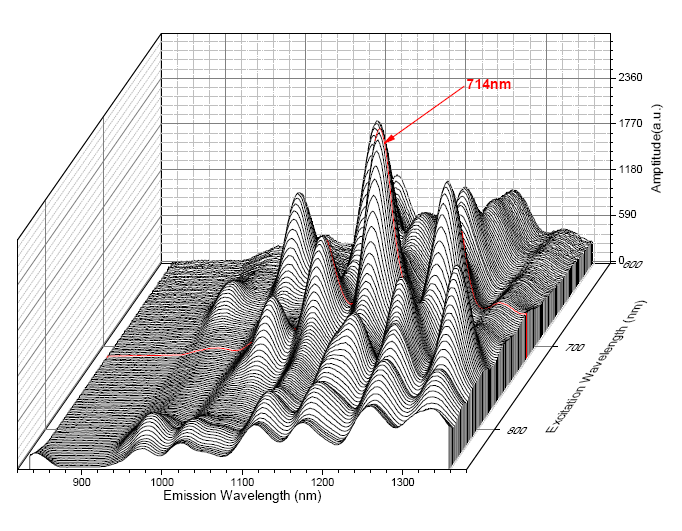
This is a simple waterfall graph to show a series of spectra in three-dimension space. Data can be XYXYXY or XYYYYY columns in worksheet and Z values put to a user-defined column label row "Z". The graph can be created from an online template, 3D XRD Waterfall
Contour & Heatmap
Origin's contour graph can be created from both XYZ worksheet data and matrix data. It includes the ability to apply a color fill and/or a fill pattern to the contours, display contour lines (equipotential lines) and contour labels, as well as adjust contour levels. A color-scale object can be included with the contour plot to serve as a legend. XY data of contour line can be extracted.
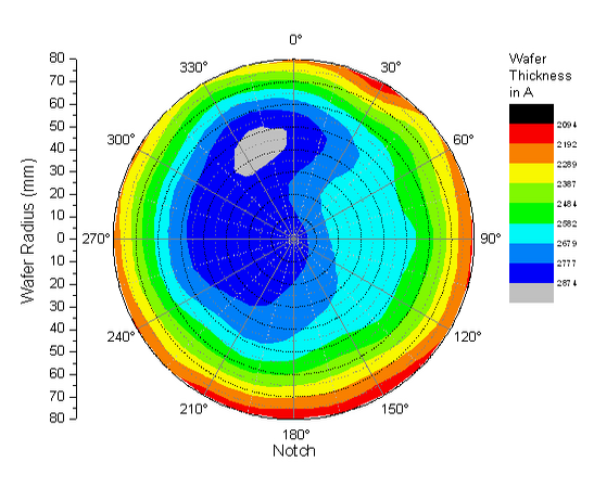
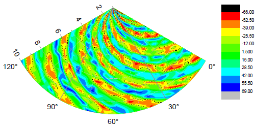
Polar contour plot of semiconductor wafer thickness measurement as a function of the wafer radius and angle. Polar contour plots can be created from data organized as "theta, radius, Z" or as "radius, theta, Z".
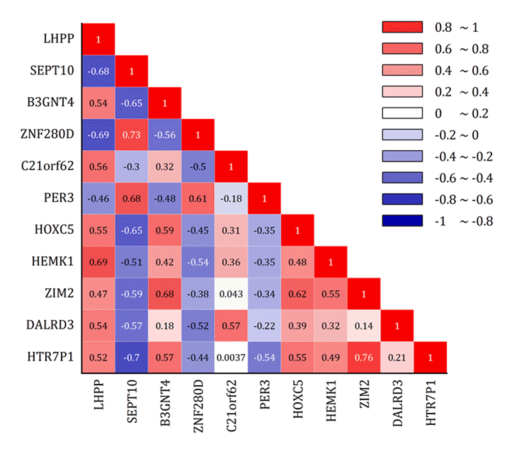
The graph displays a correlation matrix as a "lower triangular" heatmap with correlation coefficients as labels overlaid on the graph
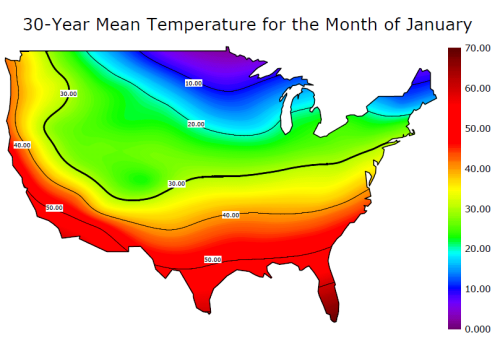
Color fill contour depicting the global mean distribution of seawater conductivity. The conductivity data stored in a matrix is plotted as a color fill contour, with contour lines hidden. The missing values in the matrix where continents are located, are colored white. A second dataset containing continent boundaries is plotted as an overlay line graph.
Contour created from XYZ columns where Z is categorical (text). A scatter plot with color map was also added to the layer.
Add gap between heatmap cells in x and/or y.
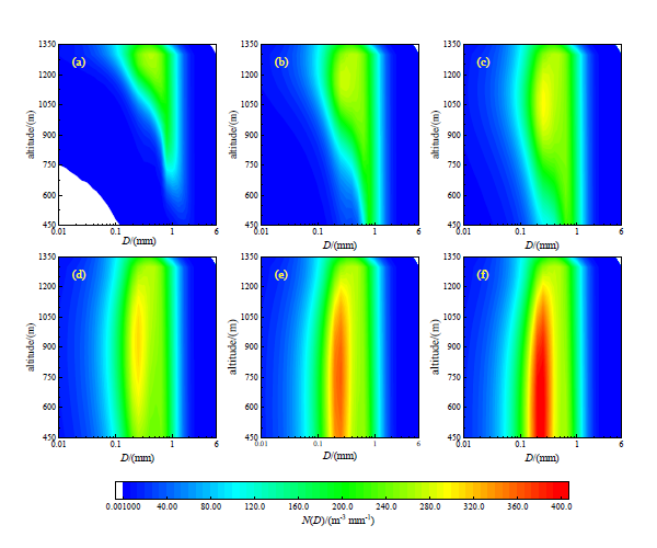
This graph is merged from 6 contour plots. The graphs simulate the change of raindrop spectra with height and time. Figures a-f respectively show the simulation results of 2, 4, 6, 10, 40, 60 min.
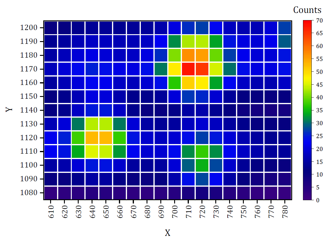
Create Heatmap plot from XYZ or XY data columns. Option to specify custom bin settings for X and Y. Generate output with counts, sum, min, max, mean, median or percent frequency.
3D Graphs 
Origin supports free transforms of 3D plots. Some transforms can be done in real time, e.g. rotation, stretching or skewing. Origin provides:
- 3D Symbol/Trajectory/Vector Plot
- 3D Basic and Stacked Bar Plot
- 3D Surface Plot
- 3D Function Plot
- 3D Ribbons/Walls Plot
- Tetrahedral Plot
- 3D Waterfall
- 3D Ternary
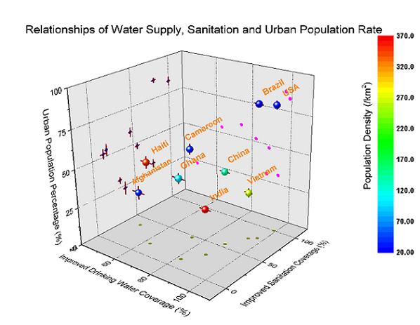
This plot shows a 3D scatter plot with x, y, z errors, and projections on three axis planes. The 3D scatter symbol is colormapped to another data column (population density). Symbols and error bars in each projection can be customized independently.
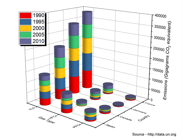
This is a 3D Stacked Bars plot, with bar shape set to Cylinder. The plot tracks emissions of three classes of greenhouse gases, in the countries of France, Germany, Canada and Japan, over the period from 1990 to 2010.
Tetrahedral plot from XYZZ data.
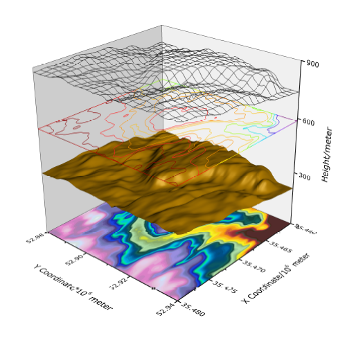
Multiple surfaces stacked in a single layer. The graph was created by plotting the same matrix data in four different styles, and offsetting them in Z direction. The four surfaces from top to bottom are wire frame, flattened contour line plot, color filled surface with lighting effect, and flattened color filled contour plot.
A surface plot created from XYZ data where the color map was based on a 4th data column. A custom XY boundary has also been applied to the plot.
Grouped Data Plot
Using grouped data, you can easily create multi-panelled graphs in Origin with a single click on the plot menu
- Cluster Plot (Line, Scatter and Column)
- Grouped Box Plot
- Grouped Column Plot
- Various Types of Trellis Plots
-
- Scatter
- Line and Symbol
- Bridge Chart
- Box
- Double - Y
- Scatter
-
- Column/Bar
- Stacked Column/ Bar
- 100% Stacked Column/ Bars
- Floating Bar
- Column/Bar
Flexible configuration and customization options include
- Control the style increments between or within the groups
- Customize the gap between, or within the groups.
- Add Gap between panels
- Wrap panels
- Overlap panels
- Uniform or Independent X/Y Scale
- By Drag-and-Drop Column Assignments (with Pre-installed App - Graph Maker)
Read More>>
More Graphs>>
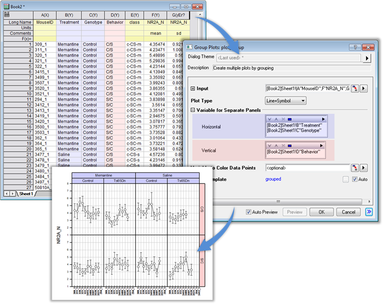
The user can easily create multi-panel graphs from grouped data with the Trellis plot.
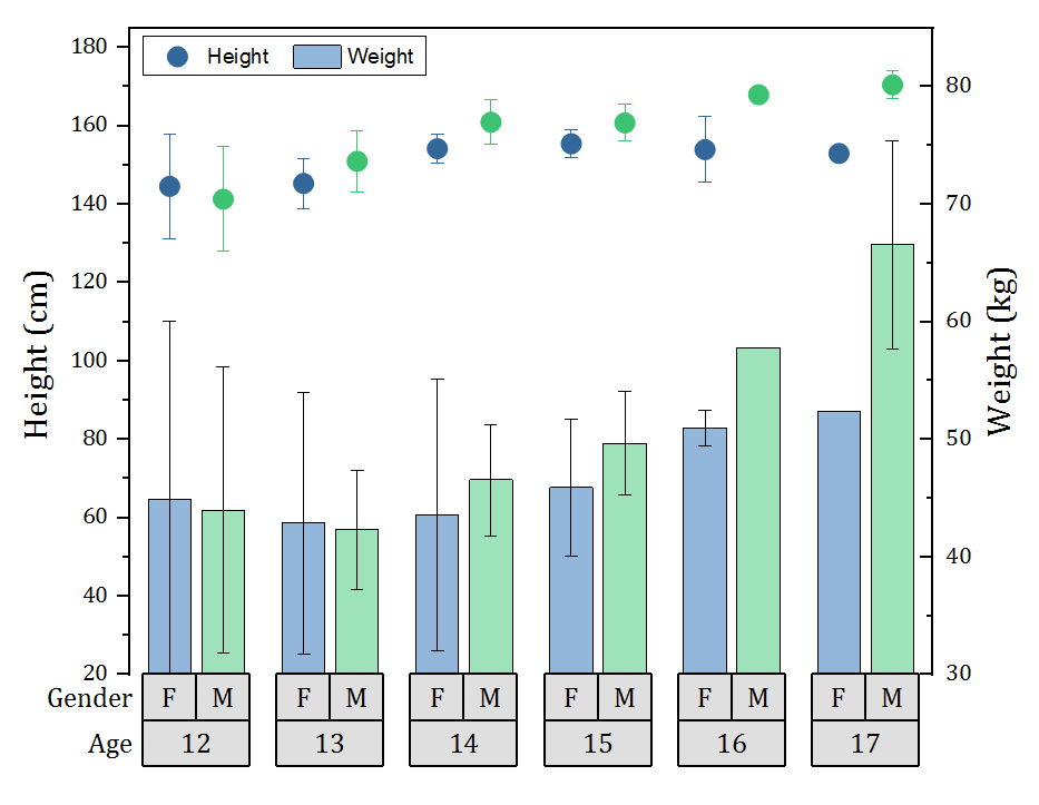
Multi-layer Cluster Plot with option for independent X and Y scales. Easily change formatting of plots and other attributes in all layers by editing properties in one layer.
Grouped plots now support scatter plot with subgroup spacing. Scatter can then be combined with other plot types such as the column plot in this example.
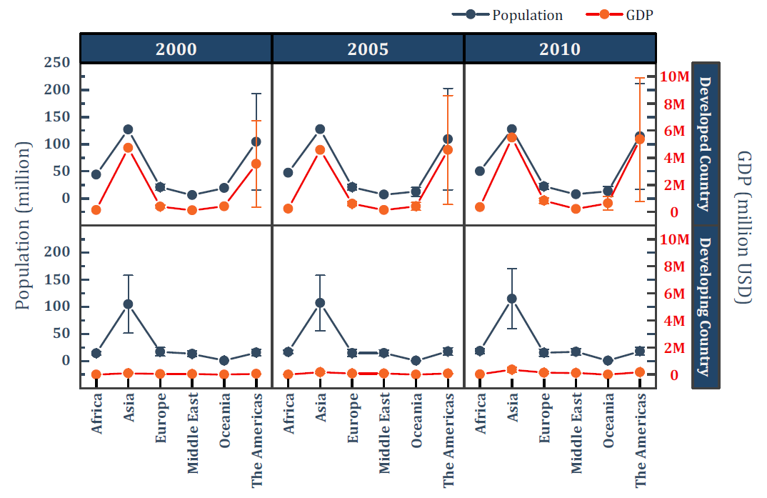
Double-Y Trellis plot with two independent Y axes, each with its own scale settings.
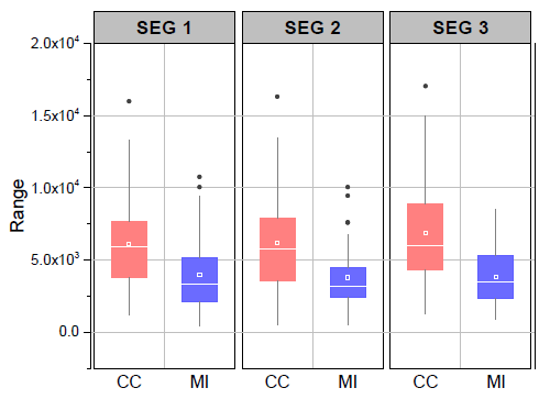
Grouped box chart with gap between subgroups. The graph was created from indexed data with two group levels. Options for customization include flexible spacing between and within subgroups, setting axis tick label as a table above or below the graph layer to display relevant grouping information, connecting mean points, data points or other percentiles and multiple box styles including column scatter, statistics bars and interval plots.
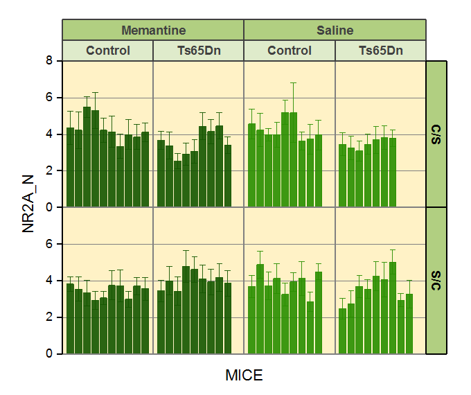
This is an example of a trellis column plot with error bars. In the trellis plot, the horizontal panels are defined by two grouping variables, treatment (Memantine v.s. Saline) and genotype (Control v.s. Ts65Dn), and the vertical panels by one grouping variable, behavior (C/S v.s. S/C).
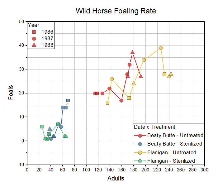
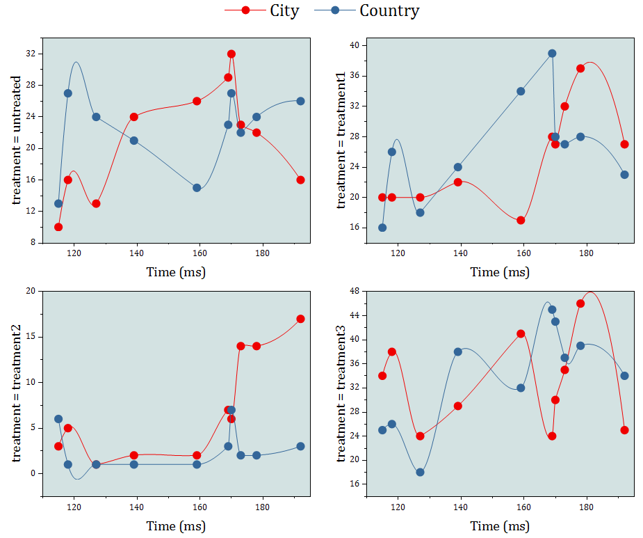
The example shows a trellis plot with the Overlap Panels option enabled. Two variables, Location and Treatment, are used to define the horizontal panels. This results in a four-panel horizontal array. By enabling the Overlap Panels option, we combine four panels into one while preserving the grouping information. Note that plot symbol color is indexed to the four Location x Treatment combinations and symbol shape is indexed to Year, as shown in the plot legends.
Categorical Special Diagrams (Parallel, Alluvial, Sankey, Chord, Network, Ribbon)
Parallel, Alluvial, Sankey,Chord, Network and Ribbon Diagrams are extremely useful to visualize flow of data, and access the relationships between the different variables.
More Graphs>>
Parallel Sets Plot with customizable plot curvature and transparency
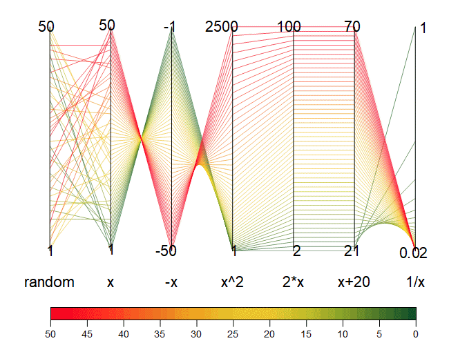
The graph displays a sample created by Yug for parallel coordinates.
It visualizes the relationship of functions of x. Each axis of the parallel plot has it's own scale range.
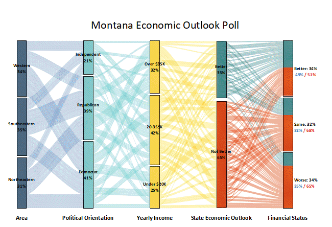
The alluvial diagram shows whether state economic outlook affects the feeling of respondent on his/her financial status. We can also see whether area, political orientation, and income of the residence in the state affects their view.
The color of nodes of financial status are indexed to the state economic outlook column so that we can clearly see the relationship of these two views.
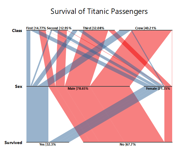
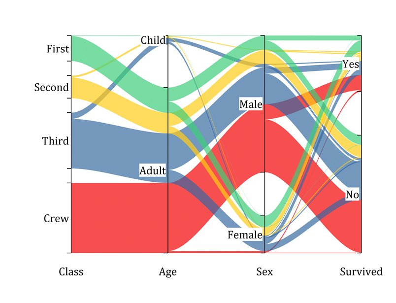
Horizontal alluvial diagram of Titanic survival data.
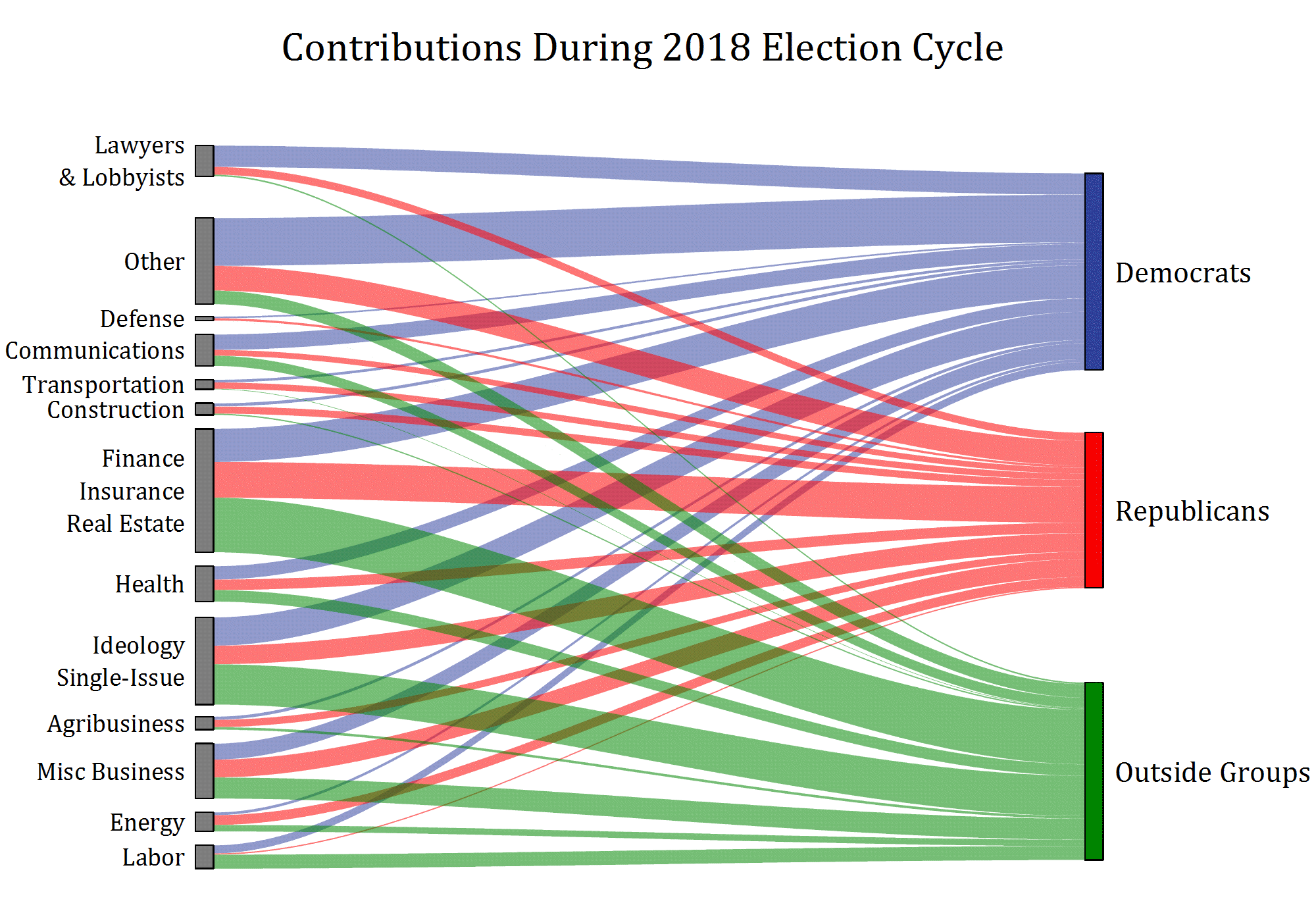
Sankey diagram of contributions from various groups during the 2018 election cycle.
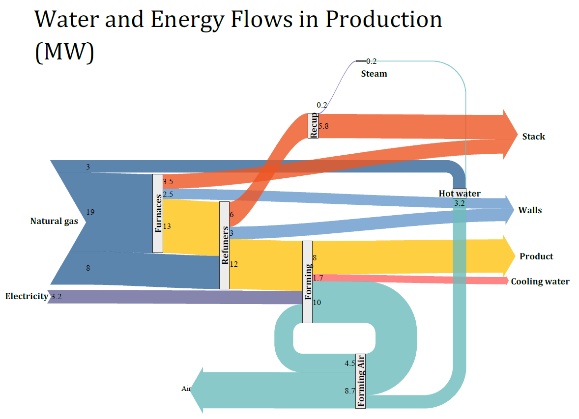
Sankey diagram showing flow of water and energy
Ribbon Chart
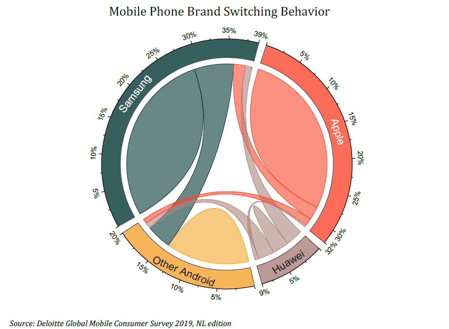
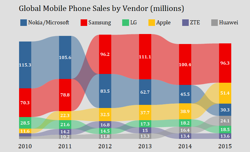
Chord diagram of mobile phone data
The Chord diagram animates global migration every 5 years from 1960 to 2010
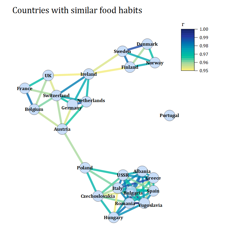
Network diagram of food preferences of countries
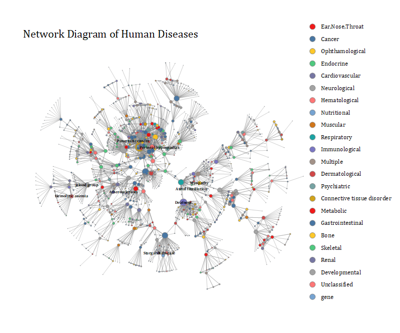
Network diagram of human diseases
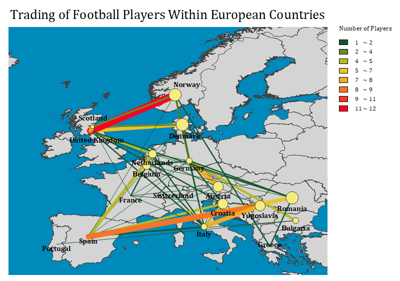
Network plot overlaid on map
Statistical Graphs
Origin supports many types of Statistical graph:
- Box Chart, Grouped Box Chart
- Histogram, Stacked Histograms
- Marginal Box/ Histogram Chart
- Histogram + Probabilities Plot
- Rug Plot
- Violin Plot
- Scatter Matrix Plot
- Bridge Charts
- Probability & Q-Q Plot
- 2D Kernel Density Plot
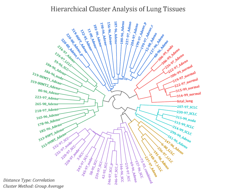
- Vertical/Horizontal/Circular Dendrogram
- Population Pyramid Plot
- QC(x bar R) Chart
- Pareto Chart
- Statistics Bars
- Interval Plot
- Before-After plot
- Bland–Altman Plot
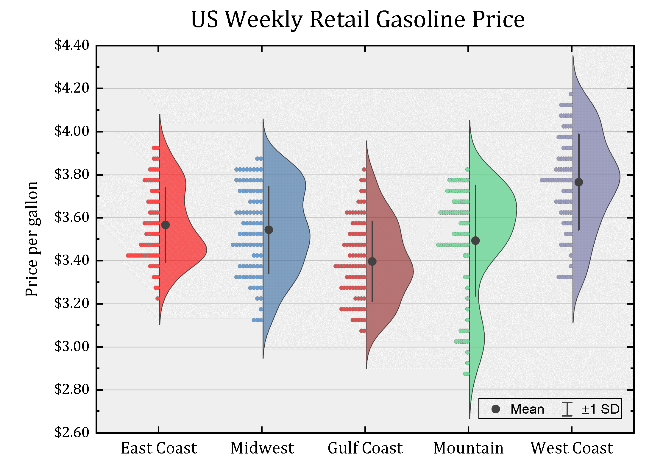
Half Violin plot displaying density distribution and data points. Visit this blog page to view more Violin plots.
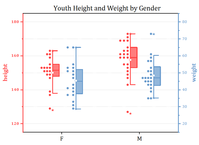
The Double-Y Half Box plot displaying box and data points, The data points are aligned in bins to show the distribution. The graph has two independent Y axes, each with its own scale settings.
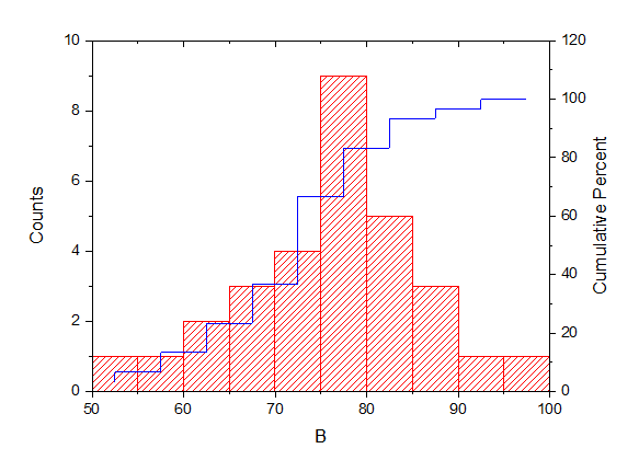
Histogram and probabilities chart: The histogram in Layer 1 provides the center, spread, and skewness of the data, while the probability plot in Layer 2 indicates whether the data follows a normal distribution.
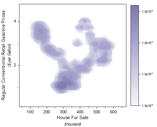
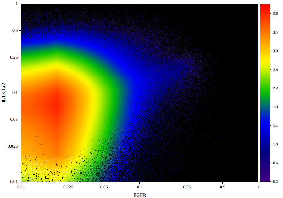
2D Kernel Density plot showing the relationship between gasoline price and houses for sale. The 2D Kernel Density plot is a smoothed color density representation of scatter plot, based on kernel density estimation. Customization options include the calculation method and flexible color-mapping with palettes.
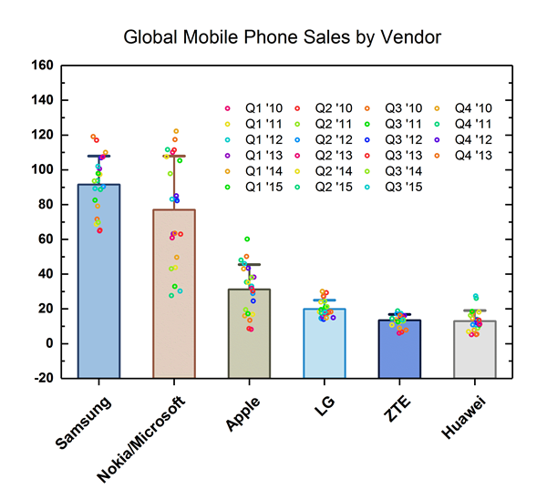
This graph displays a bar chart with data points overlapped. The bars represent the means of the datasets. Bars can be set to show other quantities (sum, median, max, etc.), using controls on the Box tab of the Plot Details dialog.
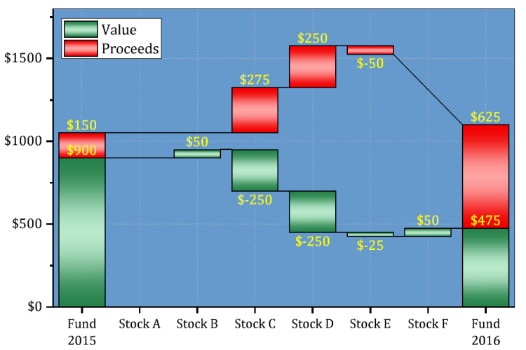
A stacked Bridge Chart displaying Value and Proceeds. Additional options include setting multiple Total columns, showing connect line, connecting by subset ect.
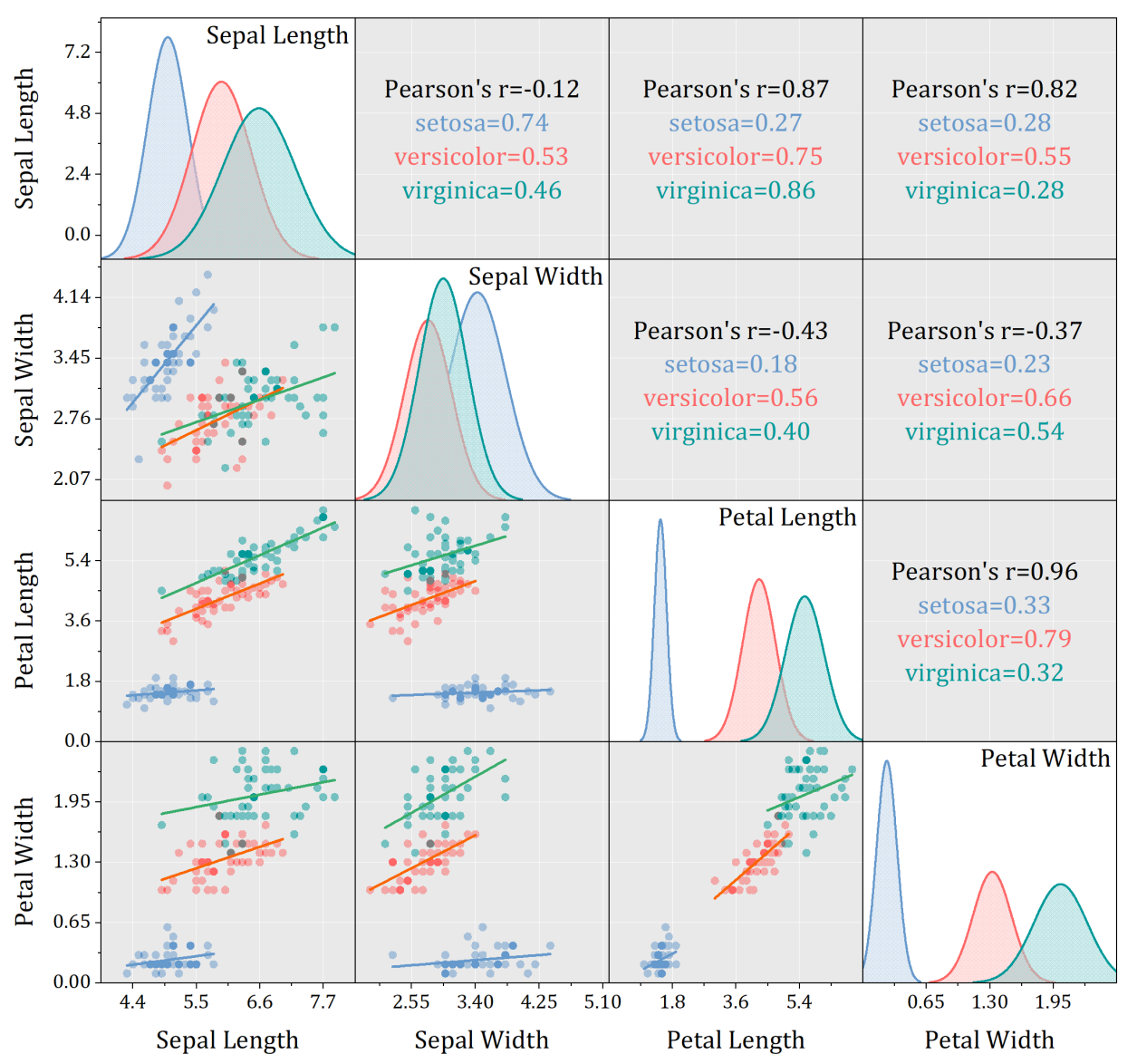
Scatter matrix with histogram in diagonal cells. A scatter matrix consists of several pair-wise scatter plots of variables presented in a matrix format. It can be used to determine whether the variables are correlated and whether the correlation is positive or negative. Customization options for scatter matrix include changing the background color of the entire window and scatter plot layers, coloring mapping scatter points by group, and hiding scatter plots on the upper/lower triangle of the diagonal.
Specialized Graphs
Origin supports many types of Specialized graph:
- Wind Rose (Binned/Raw Data)
- Radar/Spider Plots
- Bullet Chats
- Smith Charts
- Zoom Graph
- Stock Graphs
- Kite Diagram
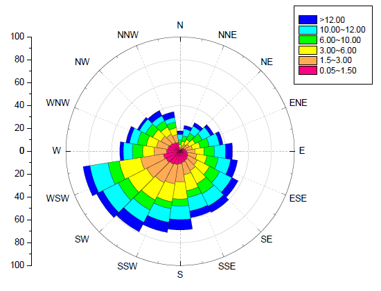
Windrose graph displaying wind speed and direction. The length of each "arm" is proportional to the fractional frequency at which wind was observed from that direction, while different colors on each "arm" indicate the wind speed. Windrose graphs can be created using both binned data and raw data and customization of the direction tick labels is supported.
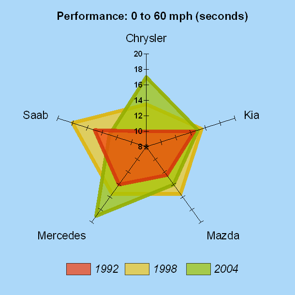
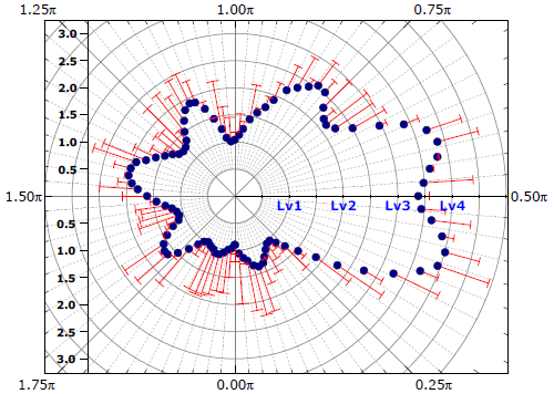
Radar chart for displaying and comparing performance of several motorcars in different years. Areas enclosed by lines are filled with incremental colors, and transparency is set to the fill color of the overlay plots for comparison. Customizations for axes include the ability to set each axis to a different scale.
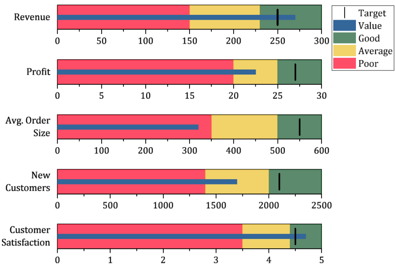
The graph displays an example of bullet chart to show performance review index.
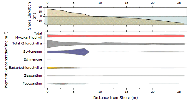
The kite diagram shows the transect of photosynthetic pigment concentrations in a hypersaline lagoon in the Bahamas
In a Zoom graph, a zoomed portion of a larger graph is added to explore a region of interest. Moving the cyan rectangle updates that portion of the graph shown by the inset.
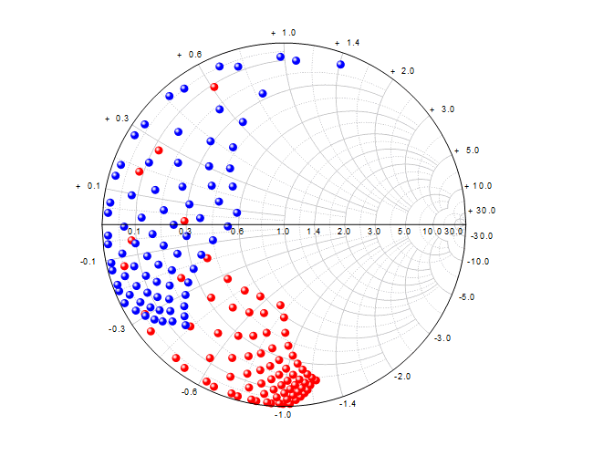
Origin can plot smith chart using z parameters directly. From Origin 2019, Smith chart supports zooming in by Scale In button
Polar and Radial Graphs
Polar and radial graphs are relevant to any phenomena characterized by its direction and distance from a fixed point, for example, temperature distribution in Earth's Polar Regions. Polar graphs are also useful for intuitive visualization of multivariate data. Origin features easy-to-use templates to display data and functions in polar coordinates, including radar and windrose diagrams.
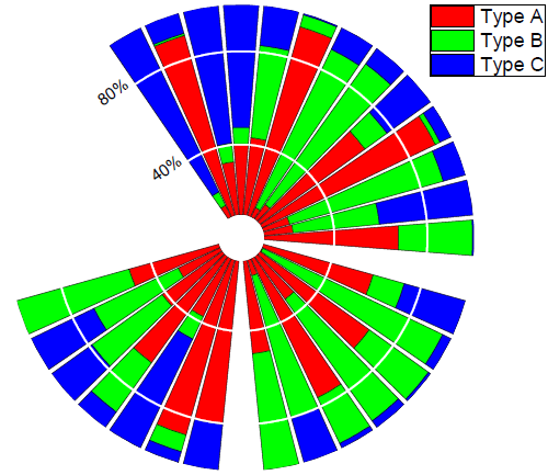
Stacked Polar Column Plot. Customization options include stacking bars of different "types", showing only one radial axis at 120 degrees, and setting the radial axis to start from a non-zero value.
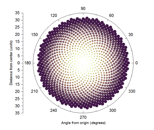
Fibonacci Sequences. The graph can be created by generating data with LabTalk scripts, plotting a theta(X) r(Y) polar graph and then mapping symbol size and color to the r and theta values.
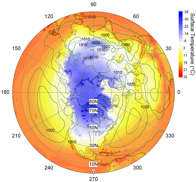
Two polar contour plots overlaid with one polar chart. This graph is created by merging three graphs, two polar contours (surface temperature as a color-filled contour and sea level pressure as green contour lines) and one polar chart (the coastline of the Northern Hemisphere) in two layers. Transparency is set to both the color-filled contour and the contour lines to make the bottom polar chart visible.
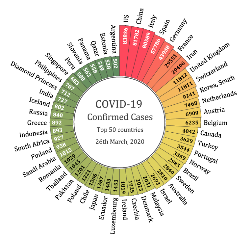
The radial bar plot shows top 50 countries of confirmed cases of COVID-19. Radial bars or stacked radial bars are also known as Nightingale Rose Chart, or Coxcomb Chart. It is to show data in circular bars.
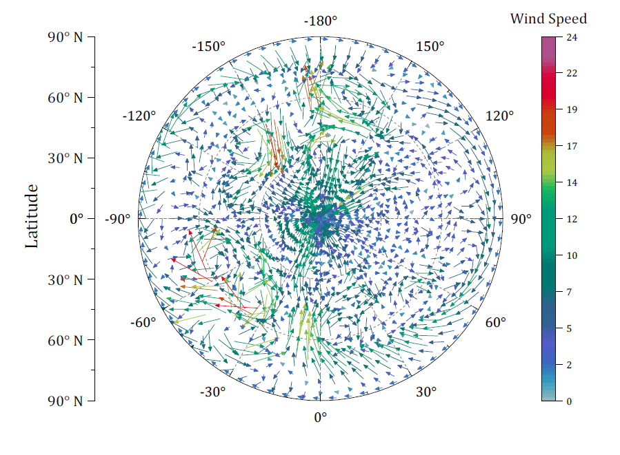
Polar vector plot of wind speed
The compass plot displays wind speed every day in March, 2015
Vector and Streamline Plots
A vector graph is a multidimensional graph used in industries such as meteorology, aviation, and construction that illustrates flow patterns (e.g. of wind, water, magnetic field), and represents both direction and magnitude at each point. Origin provides:
- 2D Vector graphs
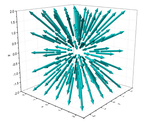
- 3D Vector graphs
- Streamline Plot graphs
This vector plot was created from data organized as X,Y, angle, and magnitude. The vector color was mapped to the magnitude values, illustrating the effect on river water flow around differently shaped pylons. The two pylons were drawn using circle object and a fill-area plot, added as a second layer.
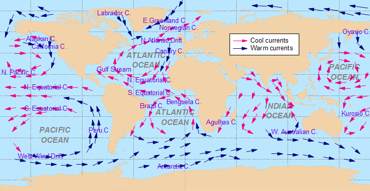
An overlay plot depicting worldwide Ocean currents. The continents were plotted as a fill area graph, with the setting "inclusive broken by missing values" selected. The warm and cool currents were graphed as vector plots with labels(data organized as X, Y, angle, and magnitude). The two graphs were then merged and superimposed.
Ternary Diagrams
Ternary diagrams are the graph type with applications primarily in the geosciences and civil engineering. Origin supports:
- 2D Ternary (with Scatter or Contour)
- 3D Ternary (with Scatter or Colormap Surface)
More Graphs>>
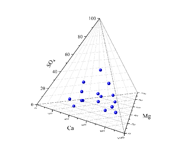
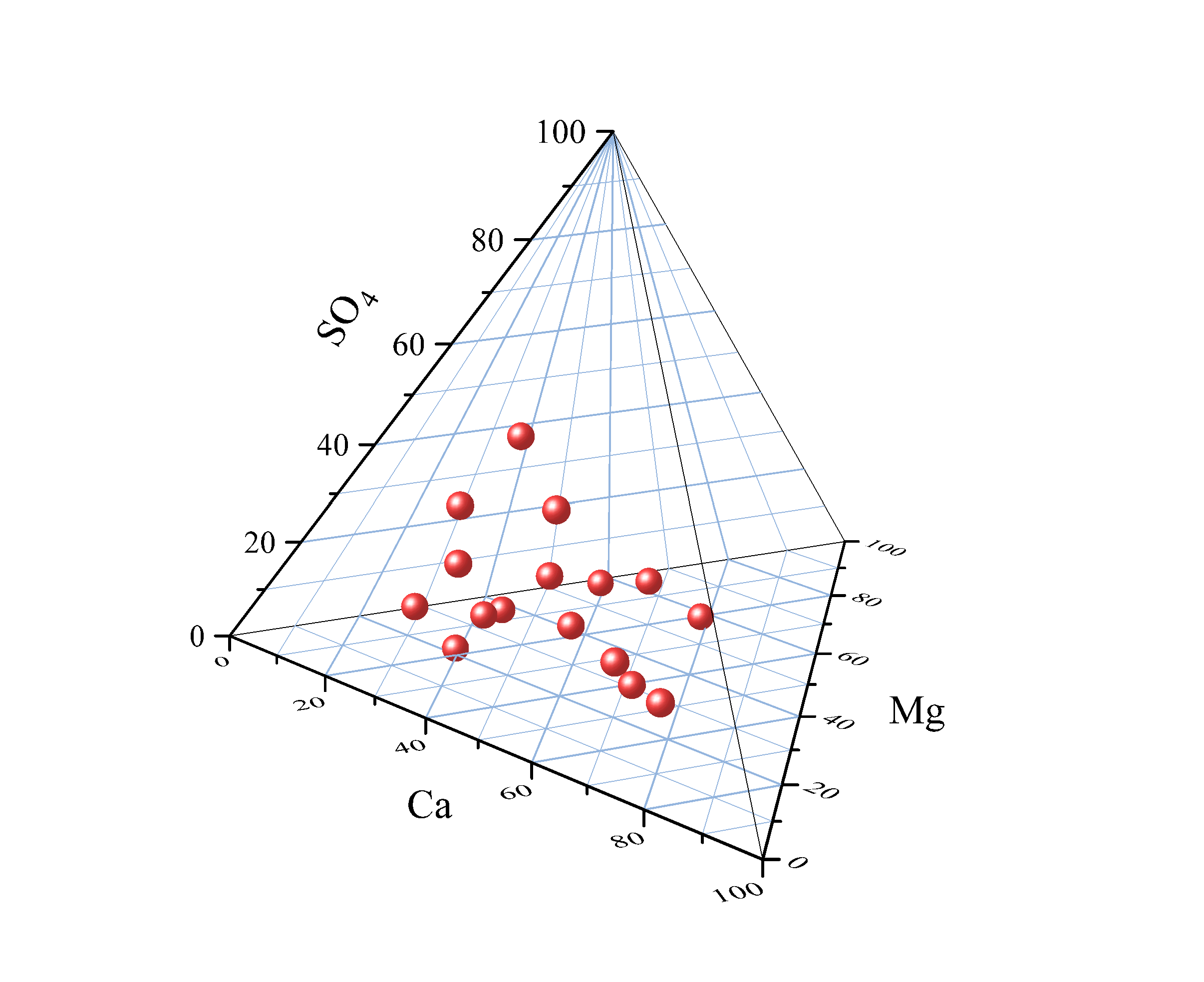
The graph shows a Tetrahedral Scatters plot, or Quaternary Phase Diagrams, created from XYZZ data.
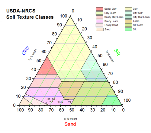
USDA soil texture triangle is created using the Soil and Rocks Classification Diagrams app. The app provides you a few popular ternary plot templates to show the relative compositions of soils and rocks. Users can overlay scatters on the templates to show classification of soil and rocks.
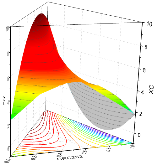
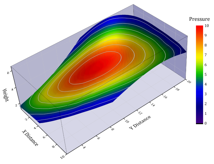
A 3D ternary surface with projection. The 3D ternary surface plot is created from a XYZZ data, while the projection at the bottom is the same surface flattened with only color-mapping contour line shown.
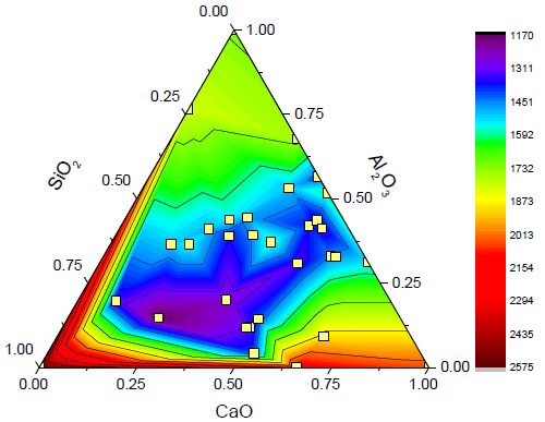
Ternary contour plot with data point overlay. The ternary contour is created from a XYZZ data, where the first XYZ is the ternary coordinates normalized between 0 and 1 while the second Z is used for color-mapping. The same first XYZ is also added as a scatter plot on top.
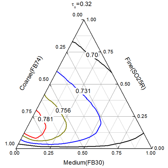
Ternary diagram of Soil Analysis Packing Fraction. Each line in this graph is created from a XYZ dataset stored in a separate worksheet. Customization options include labeling line plots with their corresponding packing fraction values and connecting data point with B-Spline line.
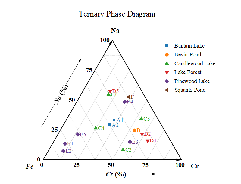
Ternary phase diagram is popular in materials science community. In this coordinate, Y and Z axes are both start at zero in same corner(X).
Hydrochemistry Diagrams
Origin supports a variety of hydrological and hydrochemical diagrams.
- Piper diagrams
- Durov Diagrams
- Stiff Diagrams
- Stiff Diagram Maps
- Schoeller Diagrams
More Graphs>>
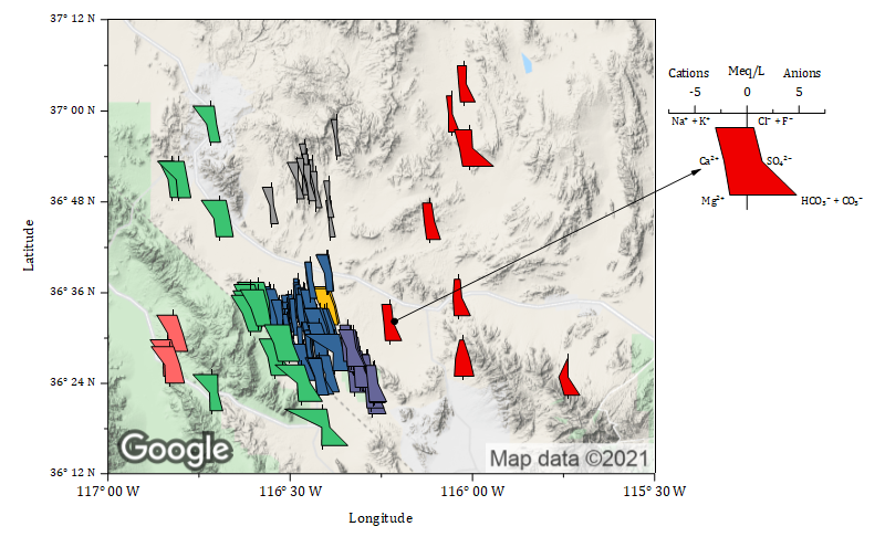
Stiff Diagram overlaid on Google Map
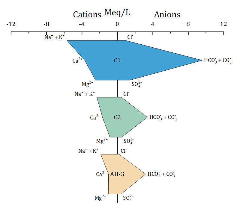
Stiff Diagram
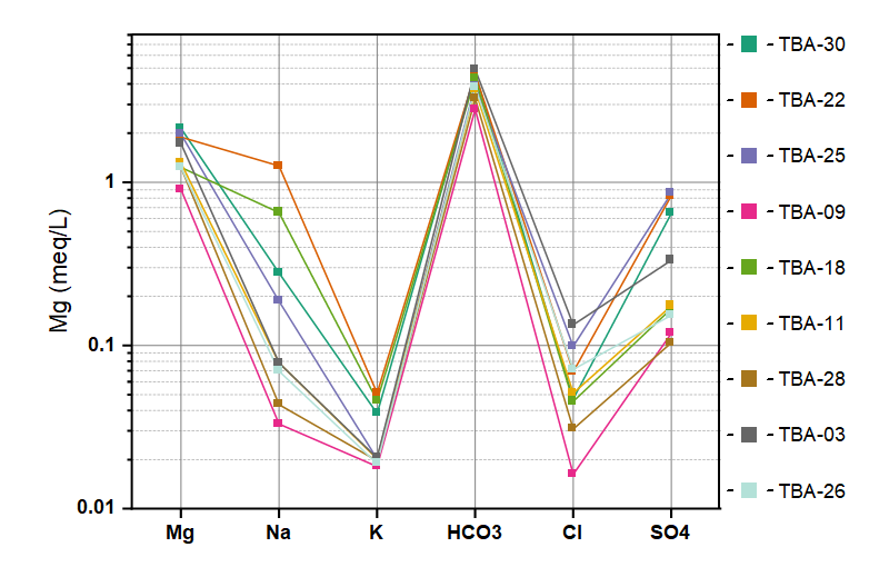
Schoeller diagram is used to show the relative concentrations of various anions and cations from multiple samples on a single graph.
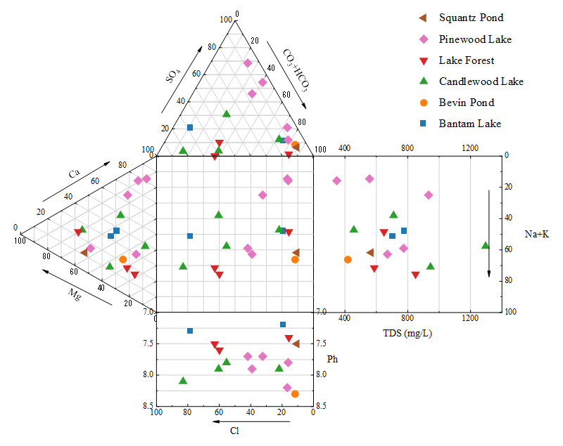
Durov Plot
Profile Plots
Origin allows you to create profiles on contour and image graphs, allowing easy inspection of vertical and horizontal cross-sections of your data.
- Profile along horizontal, vertical or arbituary lines
- Multiple profiles on the same plot
- Customize profile line width and calculate profile quantities such as min, max, mean, median, sum, and SD
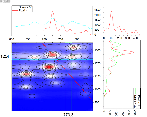
Contour profile plot. The contour profiles plot provides a dynamical way to analyze the contour data and generate profiles. Multiple horizontal, vertical or arbitrary profile lines can be added on the same contour. The thickness, color and position of the line are editable. The line and projection along this line share the same color.
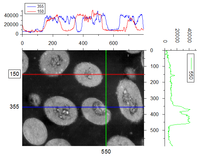
Image graph with multiple horizontal and vertical profiles/projections. The image profile plot provides a quick dynamical way of analyzing image data and generating profiles. Multiple horizontal, vertical or arbitrary profile lines can be added on the same image. The thickness, color and position of the line are adjustable, while the line and projection along this line share the same color.
Function Plot
Origin supports many types of function plots, including 2D and 3D parametric functions. 2D parametric functions are widely used in describing circles, parabolas, and hyperbolas, while 3D parametric functions describe parametric surfaces.
- 2D Function Plot
- 2D Parametric Function Plot
- 3D Function Plot
- 3D Parametric Function Plot
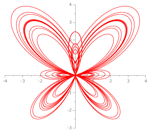
Butterfly curve created by 2D parametric function plot
X(t)=sin(t)*(exp(cos(t)))-2*cos(4*t)-(sin(t/12))^5)
Y(t)=cos(t)*(exp(cos(t)))-2*cos(4*t)-(sin(t/12))^5)
XY axes are moved to the original point.
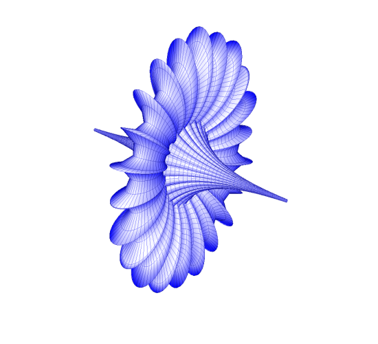
3D Parametric Function plot. All three planes and their associated axes are moved to original point, with plane grids and border turned off and directions of axes ticks changed to avoid overlapping with the surface. Lighting effect is turned on.
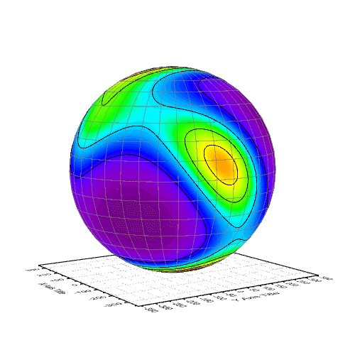
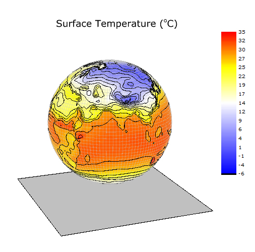
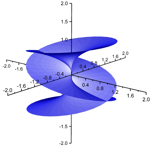
Spherical contour plot of the probability distribution of the orientation of a protein domain (regulatory light chain of myosin II) in a muscle fibre. Spherical contour plot created by two 3D parametric function plots: One is a 3D colormap surface plot and another one is a 3D surface without colormap and only shows the mesh line.
Image Graphs
Origin comes with two built-in image graph types: image plots and image profiles.
Image graph with multiple horizontal and vertical profiles/projections. The image profile plot provides a quick dynamical way of analyzing image data and generating profiles. Multiple horizontal, vertical or arbitrary profile lines can be added on the same image. The thickness, color and position of the line are adjustable, while the line and projection along this line share the same color.
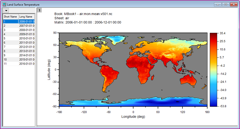
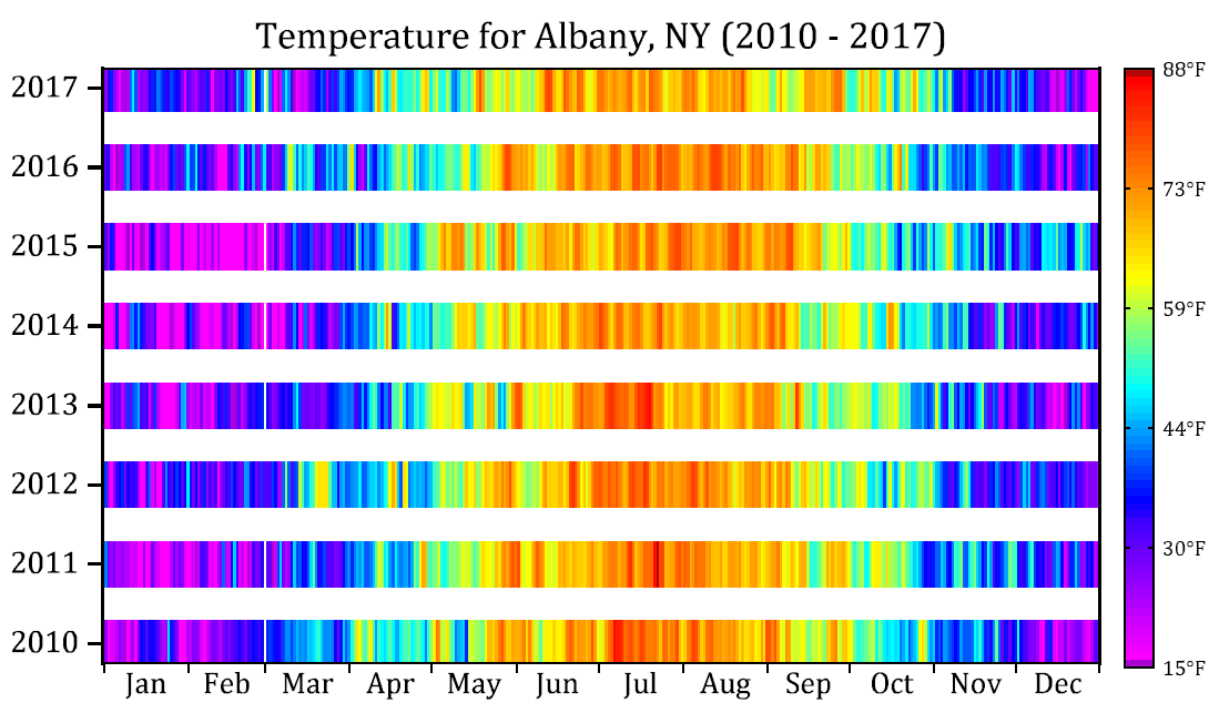
This is an image plot created from the stacked matrices to display the land surface temperature. With browser panel is on, you can flip through to show temperature changes from 2006 to 2016. The graph can be created from an online template, Climate
Graph App To Graph Pkain Design
Source: https://www.originlab.com/index.aspx?go=products%2Forigin%2Fgraphing
Posted by: chavisiont1981.blogspot.com
0 Response to "Graph App To Graph Pkain Design"
Post a Comment